
Cable Sizing & Routing
Cable sizing, schedules and optimised routing across the plant — from LV control cables to HV power cables.
Right-sized cables, cleanly routed
NEWATT sizes every cable for load, voltage drop and fault withstand, then routes and schedules it across the plant with segregation and fire safety in mind.
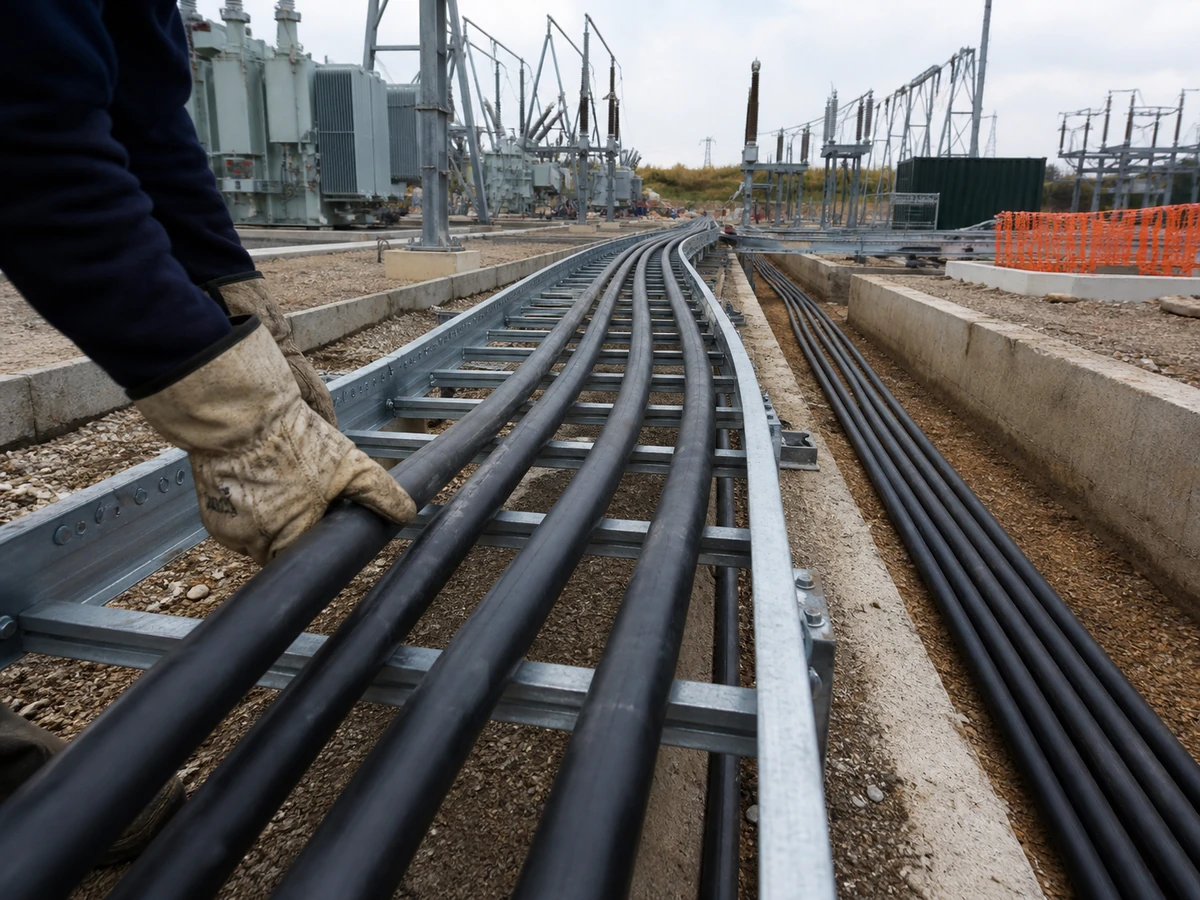
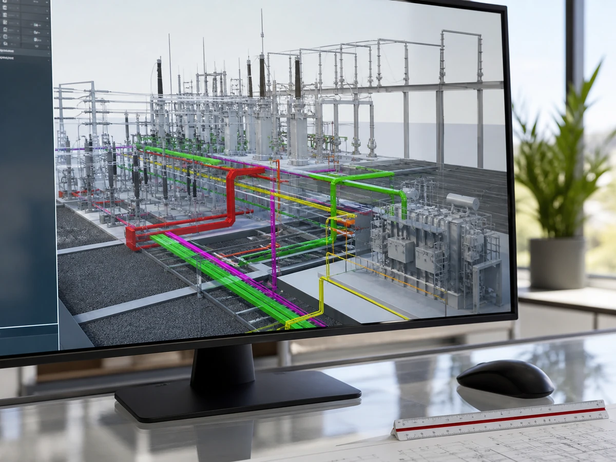
Routing is coordinated in 3D so trays and trenches are clash-free and construction-ready.
What this involves
Cables are a large part of any electrical installation, and getting them right matters for safety, losses and cost. NEWATT sizes every cable for load, voltage drop and fault withstand, then routes and schedules it cleanly across the plant.
Sizing is carried out to IEC 60287 with the correct installation derating, voltage-drop checks under steady-state and starting conditions, and short-circuit thermal-withstand verification. We then route the cables on trays, in trenches and in duct banks, keeping segregation and fire performance in mind.
The deliverables are complete cable schedules, drum lists and BOQs, together with routing designs coordinated in 3D so trays and trenches are clash-free. The site team receives a cable installation package that is right-sized, safe and ready to build without on-site guesswork.

Cable sizing
Ampacity & derating
Cable current-carrying capacity is calculated from base ampacity tables and then derated for the actual installation conditions — grouping, ambient or soil temperature, thermal resistivity and depth of burial — rather than applying base ratings that don't reflect how the cable is really installed. We apply the derating factors from the governing standard systematically across every cable in the schedule, so no cable is sized on an optimistic assumption that doesn't hold up on site.

Voltage drop
Voltage drop is calculated along the full length of every significant cable run, checked against the percentage limit the load or standard requires at both starting and running conditions, since motor starting current can push a marginal cable over the limit even when steady-state drop looks fine. Where drop exceeds the limit, we upsize the cable or adjust routing rather than accepting a marginal result, and the calculation basis is documented in the cable schedule.
Short-circuit withstand
Every cable is checked against the fault current and clearing time it would see under a short circuit, confirming the conductor and any armouring can absorb the let-through energy without thermal damage before the protective device clears the fault. This calculation is cross-checked against the protection coordination study, since a cable sized correctly for ampacity can still fail thermally if upstream protection is too slow to clear a fault within the cable's withstand rating.
Standards (IEC 60287)
Cable ampacity and derating calculations are carried out to IEC 60287, the governing standard for continuous current rating of cables, with installation-specific correction factors applied rather than generic multipliers. Where a project specifies a different standard — NEC ampacity tables, for example — we work to that standard instead and document which one governs. Calculation sheets are structured so a reviewing engineer can trace every input back to its source.
Routing & schedules
Tray & trench routing
Cable tray and trench routes are designed to keep runs as short and direct as practical while maintaining separation between power and signal cables, bend radius limits and fill percentages within the tray manufacturer's ratings. We coordinate routing with the civil and structural design so trenches, tray supports and penetrations are shown on the same drawings the civil team is building from, avoiding the clashes that come from routing being designed in isolation.
Cable schedules & BOQs
Every cable in the project is captured in a structured schedule — source, destination, size, length, type and installation method — that becomes the single reference procurement, installation and commissioning teams all work from. We generate bills of quantities directly from the schedule so material takeoffs are consistent with the design rather than estimated separately, and update the schedule through design changes so it stays accurate right through to as-built.
Segregation & fire
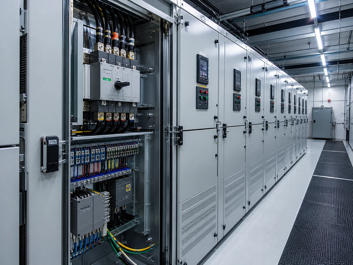
Power, control and instrumentation cables are segregated per the relevant standard to avoid electromagnetic interference and to limit fire spread between cable groups, with segregation distances and barrier requirements shown explicitly on routing drawings. Fire-rated cable, fire stopping at penetrations and fire barriers along cable routes are specified where the project's fire strategy requires them, coordinated with the fire engineer rather than applied as a generic default.
3D routing & clash
Cable routes are modelled in 3D alongside structural, mechanical and other electrical elements, so clashes between tray routes, ductwork, structural steel and equipment are caught and resolved before construction rather than discovered on site. We run clash detection at each major design stage, track resolution of every clash to closure, and issue coordinated routing drawings that reflect the clash-checked model rather than a 2D drawing produced independently of it.
Have a scope in this area?
Share your requirements and we'll respond with a defined scope, programme and fixed fee — typically within two working days.
Request a proposal