
HVAC Engineering
Heating, ventilation and air-conditioning design for control rooms, switchgear buildings and industrial facilities — sized from real heat-load calculations, not rules of thumb.
Cooling designed around the equipment it protects
NEWATT designs HVAC systems for control rooms, switchgear and relay rooms, battery rooms and site offices — spaces where the wrong cooling design means nuisance trips or shortened equipment life, not just discomfort.
Because we already know the electrical equipment's heat dissipation from the same design that sized the switchgear, HVAC capacity is calculated from the actual load the room will carry rather than a generic area-based rule of thumb.
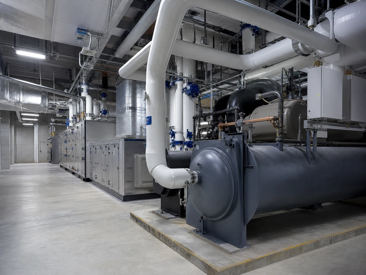
What this involves
HVAC for an industrial or utility site is rarely about comfort cooling alone — control rooms, relay panels, battery rooms and switchgear buildings all generate heat that has to be removed reliably, since nuisance equipment trips or shortened service life are the real cost of undersized cooling.
We calculate room heat loads from the actual equipment installed — switchgear losses, battery charging heat, relay panel dissipation — combined with solar and occupancy loads for the building envelope, then size air handling units, chillers or split systems to match, with N+1 redundancy where the room's criticality requires it.
Ductwork, piping and equipment layouts are coordinated with the electrical and civil design in the same 3D model, so HVAC routing doesn't clash with cable trays, structural members or maintenance access paths.
The HVAC scope

Heat load calculations
Room heat loads are calculated from the actual equipment installed — switchgear and relay panel losses, battery charging heat, transformer room dissipation — combined with solar gain, occupancy and envelope loads, rather than an area-based rule of thumb that can significantly under- or over-state real cooling demand. Calculations follow ISHRAE methodology and are documented so the basis for every AHU or split-unit selection is traceable.
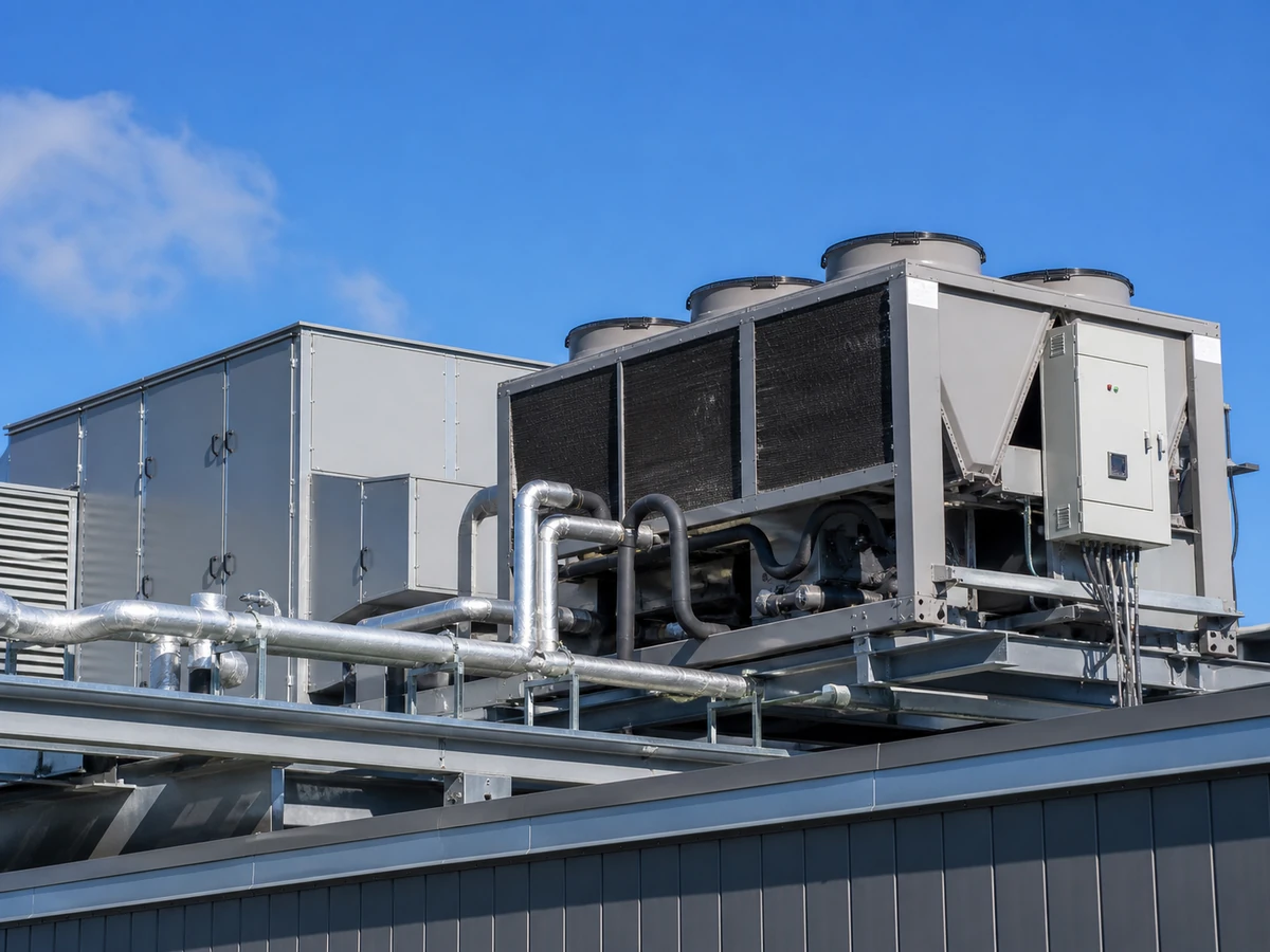
AHU, chiller & split system sizing
Air handling units, chillers and split systems are selected and sized from the calculated heat load for each space, with redundancy — N+1 or 2N — specified for rooms where a cooling failure would trip protection-critical equipment. Equipment selection accounts for ambient design conditions specific to the site, not a generic default, since a system sized for a mild climate will under-perform in a hotter one.
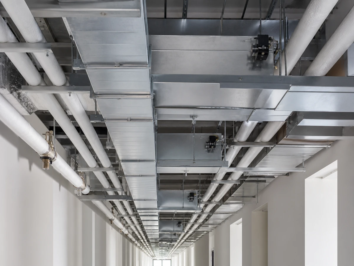
Ductwork & piping design
Ductwork routing, sizing and insulation are designed for the actual air quantities the load calculation requires, with duct sizing checked against velocity and pressure-drop limits rather than assumed from equipment nameplate airflow. Chilled-water or refrigerant piping is sized and routed alongside the ductwork, coordinated with the building's structural and electrical layout to avoid clashes.
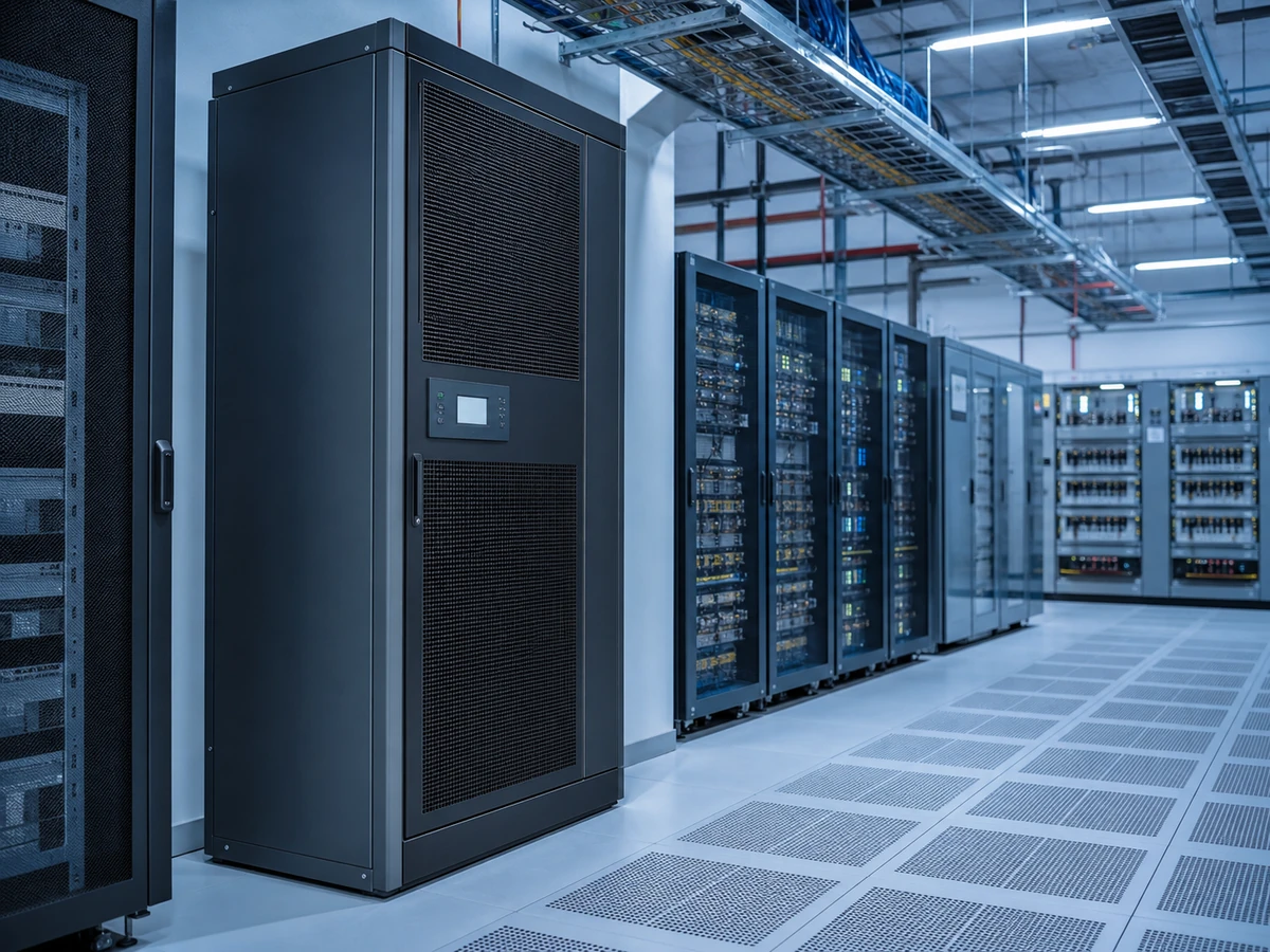
Control room & data centre cooling
Cooling for control rooms, data halls and switchgear buildings is designed for continuous, unattended operation — tight temperature and humidity bands, N+1 redundancy and alarm interfaces to the building's SCADA or BMS — rather than treated as standard comfort air-conditioning. We coordinate cooling capacity with the electrical load growth the room is designed for, so the HVAC system doesn't become the constraint on future equipment additions.
Standards & analysis

ISHRAE compliance
HVAC design follows ISHRAE handbook methodology for load calculation, system selection and ventilation rates, with the specific design conditions, occupancy assumptions and standards referenced documented alongside the calculation. Where a project specifies an alternative standard — ASHRAE, for example — we design to that standard instead and note which one governs.
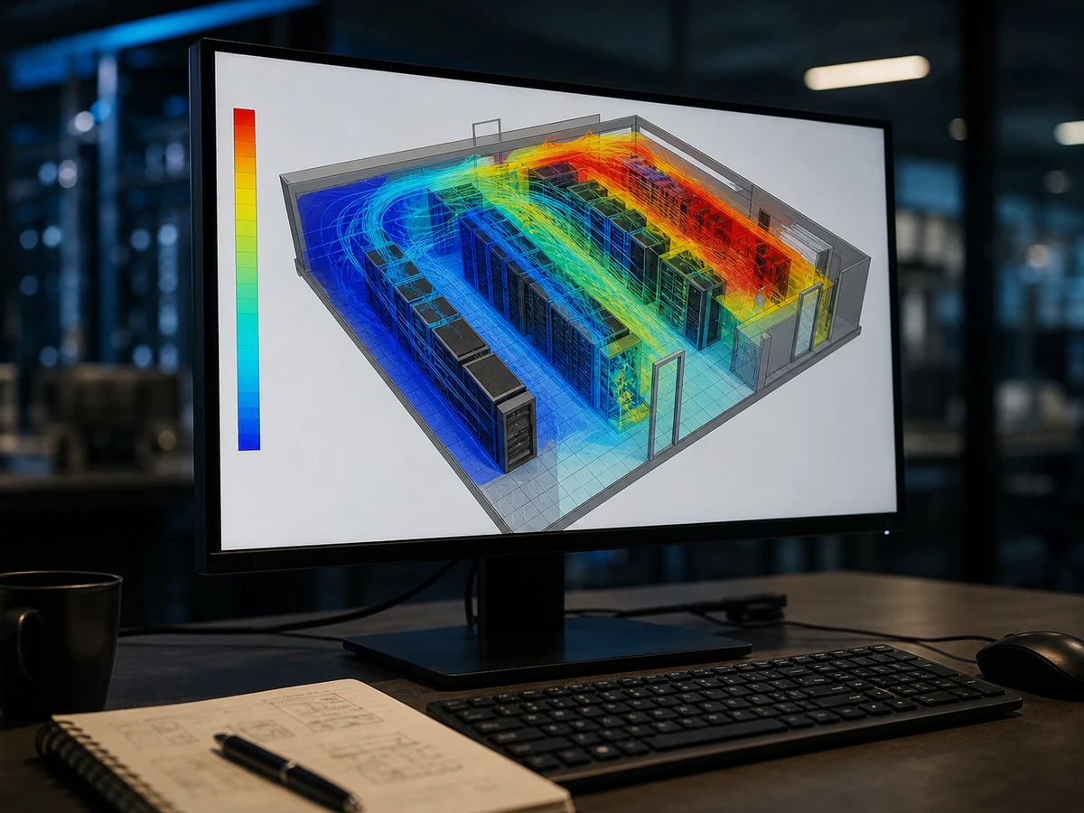
CFD & airflow analysis
For critical spaces — dense switchgear rooms, data halls, battery rooms — we run computational fluid dynamics analysis to confirm airflow actually reaches the equipment that needs it, rather than assuming a uniform room temperature from the load calculation alone. CFD results identify hot spots and recirculation before installation, so diffuser placement and airflow rates can be corrected on the drawing rather than on site.
Planning a critical-space cooling system?
Share your requirements and we'll respond with a defined scope, programme and fixed fee — typically within two working days.
Request a proposal